basic phasor diagram electric circuit
Why is Power Factor of Transformer is Poor at no Load? - Electrical Volt we have 9 Pics about Why is Power Factor of Transformer is Poor at no Load? - Electrical Volt like Equivalent Circuit of Transformer Referred to Primary and Secondary, Why is Power Factor of Transformer is Poor at no Load? - Electrical Volt and also Equivalent Circuit of Transformer Referred to Primary and Secondary. Here you go:
Why Is Power Factor Of Transformer Is Poor At No Load? - Electrical Volt
 www.electricalvolt.com
phasor transformer
Implement Phasor Model Of Variable Speed Doubly-fed Induction Generator
 www.mathworks.com
induction fed doubly generator turbine wind power flow mathworks ref block type physmod powersys help phasor sps variable speed
One Dark And Two Bright Lamp Method Of Synchronism With Sketches And
 www.deepakkumaryadav.in
synchronism phasor improper synchronising phaser
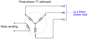
Polyphase Power Systems | AC Electric Circuits Worksheets
 www.allaboutcircuits.com
phase generator polyphase power three schematic winding rotor systems ac diagram connected shown allaboutcircuits voltage
Equivalent Circuit Of Transformer Referred To Primary And Secondary
 electricalacademia.com
transformer circuit equivalent secondary primary phasor side referred parameters form voltage electrical resistance fig ratio electricalacademia components
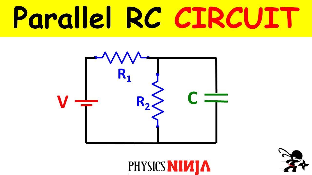
Fun Practice And Test: Capacitive Circuit Analysis
 fun-practice-test.blogspot.com
capacitor resistor resistors
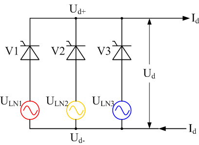
Half Wave & Full Wave Rectifier: Working Principle, Circuit Diagram
 electricala2z.com
rectifier rectificador rectification trifase controlado voltage circuito dreiphasen trifásico bearbeiten modifier gprectifier semionda
☑ Diode For Ac Application
 alboepoodlegeorge.blogspot.com
diode rectifier
How Do Digital Thermometers Work ? TRANSDUCERS - BLOCK DIAGRAM
 www.pinterest.com
Fun practice and test: capacitive circuit analysis. Why is power factor of transformer is poor at no load?. Phasor transformer