bridge rectifier wiring diagram
1.25V to 120V Mains Adjustable Voltage Regulator Circuit | Homemade we have 9 Images about 1.25V to 120V Mains Adjustable Voltage Regulator Circuit | Homemade like #bridgerectifiertest ||Three phase rectifier TEST || How to check, Electrical Engineering World: The Practical Way of Wiring the Three and also The Silicon-Controlled Rectifier (SCR) | Thyristors | Electronics Textbook. Read more:
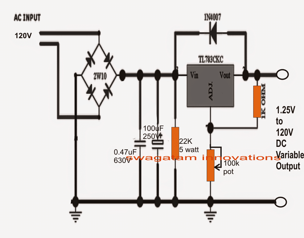
1.25V To 120V Mains Adjustable Voltage Regulator Circuit | Homemade
 www.homemade-circuits.com
circuit voltage adjustable 120v regulator diagram mains 25v power datasheet ic circuits homemade supply variable charger battery electronic short build
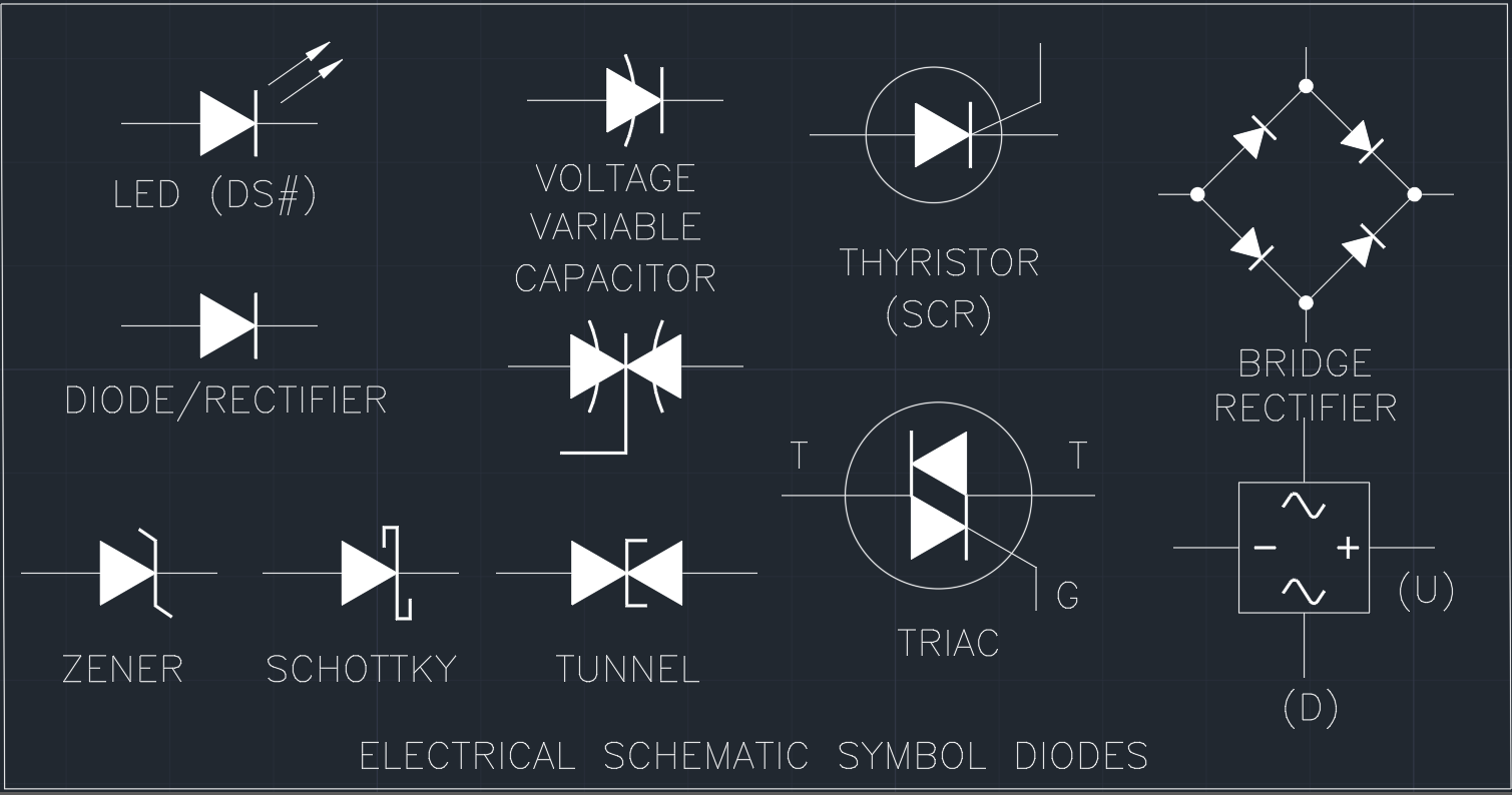
Power Supply Symbol | | Free CAD Blocks And CAD Drawing
 www.linecad.com
diodes autocad input
Cub Cadet 2140 Wiring Diagram
 www.mikrora.com
cadet cub diagram wiring 2140 2166 sponsored links
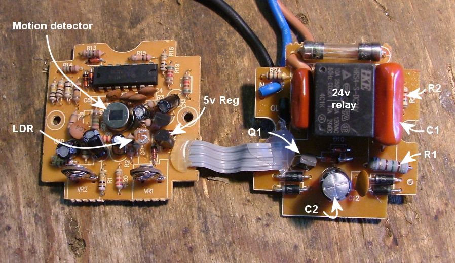
TheBackShed.com - 12v Sensor Light
 www.thebackshed.com
sensor light circuit motion diagram detector pir wiring volts lens thebackshed 12v test windmill articles
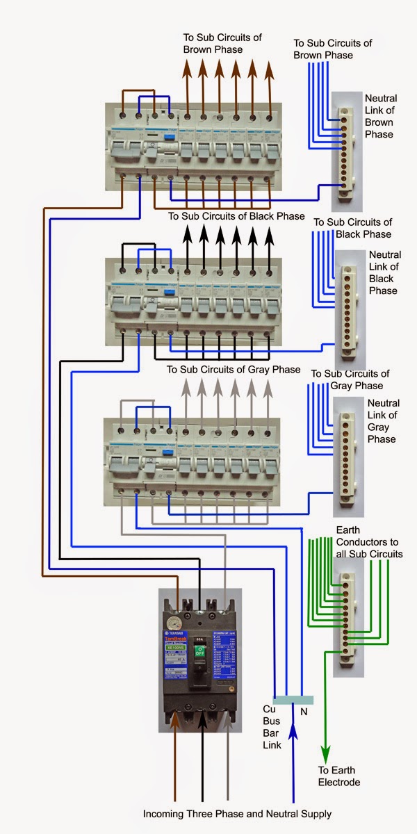
Electrical Engineering World: The Practical Way Of Wiring The Three
 electrical-engineering-world1.blogspot.com
phase three wiring diagram distribution
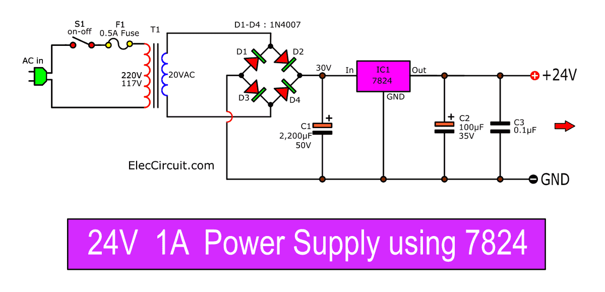
0-24V Variable Power Supply Circuit Diagram / Dual Adjustable Variable
 wiring02.blogspot.com
regulated eleccircuit lm337 lm317 transformer
Wiring Diagram For Tohatsu Charge Rectifier
 wiringall.com
tohatsu rectifier
#bridgerectifiertest ||Three Phase Rectifier TEST || How To Check
 www.youtube.com
rectifier
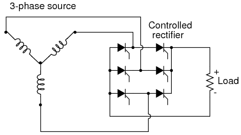
The Silicon-Controlled Rectifier (SCR) | Thyristors | Electronics Textbook
 allaboutcircuits.com
scr rectifier controlled silicon phase control bridge three circuits load electric pulse semi thyristors triggering electronics scrs
Cub cadet 2140 wiring diagram. Phase three wiring diagram distribution. Wiring diagram for tohatsu charge rectifier